Volvo EX30/EX60 V2L adapter parameters
Over time I bought several V2L adapters for my Volvo EX30, hoping one of them would work (even before software version 2.x), but none ever did. When the official V2L adapter became available (part no. 32411386), I ordered it immediately. This post isn’t about the official adapter, though. It’s about its electrical parameters, so you can build one yourself.
Disclaimer: Building your own adapter may void your car’s warranty, and you can seriously hurt yourself, because you’ll be working near wires carrying mains voltage. Everything here is provided as is, and I take no responsibility for any damage to your car, your equipment, or yourself. You’ve been warned.
I reverse engineered the connection from measurements and validated it by building my own version. I never opened the official adapter, because it didn’t look like that could be done non-destructively. So take this with a grain of salt: it works for me, YMMV (no pun intended).
In its normal state, the adapter has about 348 Ω between PP and PE. When you press and hold the push button on the adapter, the resistance rises to 1029 Ω. The button is how you start and stop discharging. The CP pin isn’t used at all, so you can leave it unconnected. There are multiple ways to get this behavior; I went with what seemed most straightforward (and with the resistor values I had at hand).
I took a 330 Ω resistor (I didn’t have anything closer, and 330 Ω seemed within tolerance 😎) and connected it in series with a 680 Ω resistor between PP and PE. Then I wired a normally closed (NC) push button across the 680 Ω resistor. Normally the button shorts it out, so the car sees 330 Ω; pressing the button opens the bypass and the car sees 1010 Ω.
PP ─ [348 Ω] ─┬─ [681 Ω] ─┬─ PE
              │           │
              └──── NC ───┘
With this simple circuit, pressing the button (the car must be unlocked) makes the car lock the adapter in place, and within a few seconds there’s 229 V between L1 and N. Pressing the button again stops discharging and unlocks the adapter.
Here’s a picture of my validation setup (yes, I taped the crocodile clips on L1 and N for safety 🙂).
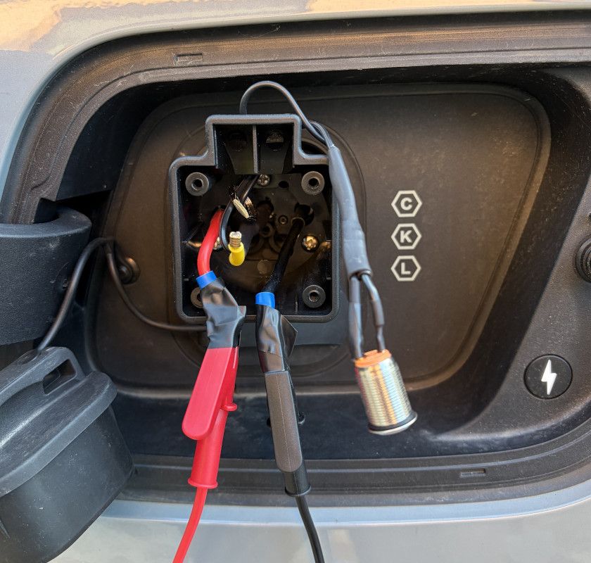
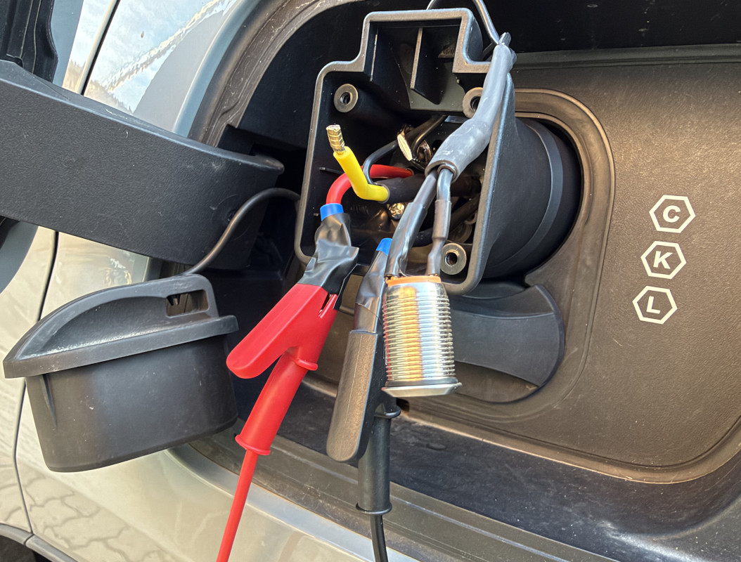
That’s really all it takes: no CP signaling, no microcontroller, just two resistors and a button between PP and PE. If you’re going to use it for more than a quick test, put it in a proper enclosure, use resistors with some power headroom, make sure the L1/N/PE side is properly rated for mains, and double-check your wiring before plugging it into the car. Happy discharging!
